Home >> Optics, convex lenses
types |
|||
Types of lens
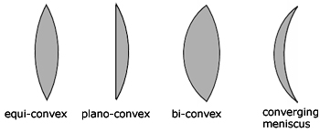
All four types of convex lens are converging lenses. That is, they bring parallel rays of light to a focus, producing a real image.
Basic ray diagram
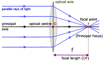
The basic ray diagram for a convex lens introduces a number of important terms:
principal axis - the line passing through the centres of curvature of the lens
principal focus - a point on the principal axis where rays of light parallel to the principal axis converge
focal length - the horizontal distance between the principal focus and the optical centre of the lens
optical centre - an imaginary point inside a lens through which a light ray is able to travel without being deviated
centre of curvature - the centre of the sphere of which the lens surface is part
Power of a lens
![]()
The power P of a lens is the inverse of its focal length f. Since f is measured in metres 'm' the units of lens power are m-1.
The power also depends on the type of lens. Convex lenses have positive powers, while concave lenses all have negative powers.
For example, a 10 cm focal length convex lens has a power of +10 m-1; while a 20 cm focal length concave lens has a power of -5 m-1.
Ray diagrams
To understand ray diagrams it is important to know something about images. Images come in two categories :
real images - are produced from actual rays of light coming to a focus (eg a film projected onto a screen)
virtual images - are produced from where rays of light appear to be coming from (eg a magnifying glass image)
Ray diagrams are constructed by taking the path of three distinct rays from a point on the object:
note - the lens is considered to be so thin as to be represented by the axis of the lens(green)
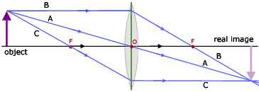
A) a ray passing through the optical centre of the lens
B) a ray parallel to the principal axis, which refracts through the lens, passing through the principal focus
C) a ray passing through the principal focus(on the same side as the object) and being refracted through the lens, emerging parallel to the principal axis
The diagrams represent the formation of an image from an object positioned between f and the lens, at f, between f and 2f and at 2f from the lens
object between f and the lens (magnifying glass)
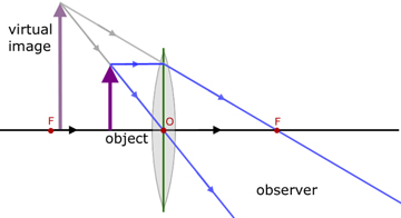
The image is the same side of the lens as the object and is upright, virtual and magnified.
object at f
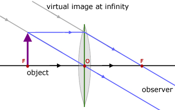
The image is formed at infinity from parallel rays that do not converge. Therefore no image is formed.
object between f and 2f (projector)

The image is on the opposite side of the lens than the object. It is real, inverted and magnified.
object at 2f
The diagram is very similar to the one showing the three construction rays.
The image is the same distance behind the lens as the object is infront.
The image is inverted, real and the same size as the object.
object at infinity
The image is formed at the focal point of the lens. It is real, inverted and diminished in size.
The Lens Formula
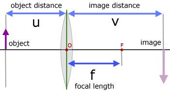
![]()
When using this equation a sign convention must be obeyed:
Distances from lenses to real objects & real images are positive
Distances from lenses to imaginary objects and imaginary images are negative.
Focal lengths of convex lenses are positive.
Focal lengths of concave lenses are negative.
The focal length f of a lens can be found quite accurately by moving an illuminated object infront of a lens so that an image is cast on a screen. By taking readings of image and object distances for different positions, a graph can be drawn.
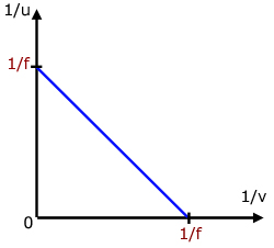
Plotting 1/u against 1/v gives a straight line with a negative gradient. The focal length can be found from the intercept, which is 1/f on both the x and y axes.
Magnification
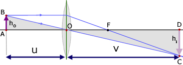
Magnification (m) is simply the image height divided by the object height.

To obtain a relation involving object distance (u) and image distance (v), consider the image formed by two rays from a point on the object.
Triangles AOB and COD are similar.
Therefore,
![]()


Chromatic Aberration
Chromatic aberration is the dispersion of white light by a convex lens. The different coloured components of white light are brought to different foci according to their wavelength. Since 'red rays refract least', red light produces the longest wavelength and violet the shortest.
In the diagram, FB , FG , FR are the principal foci for blue, green and red light.
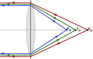
Chromatic aberration affects the image by making it appear blurred with fringes of colour around it. This is a result of only one colour being in focus at a time.
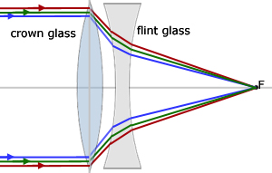
Chromatic aberration can be corrected using a chromatic doublet. This is a combination of two lenses, one convex and the other concave. The lenses are of different types of glass (crown glass & flint glass) . The pair are cemented together (not shown) using Canada Balsam glue. This has a refractive index mid-way between the two glass types. In any event, the glue layer is extremely thin and has little effect.
[ About ] [ FAQ ] [ Links ] [ Terms & Conditions ] [ Privacy ] [ Site Map ] [ Contact ]
