Home >> Fields, capacitors 2
energy stored |
Energy stored in a capacitor
The energy stored in a capacitor is in the form of electrical potential energy. This is has two components:
work done in adding electrons to the negative plate
work done in removing electrons from the positive plate
Consider a partially charged capacitor, with a p.d. of V volts across it and charge Q on it plates.
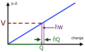
Now during charging, consider a small charge δQ moving from one plate to another. If δQ is very small then the increase in p.d. is also very small. So V may be considered approximately the same.
Hence the work done δW , is given by :
![]()
Recalling the equation for capacitance C and rearranging to make V the subject :
![]()
![]()
Substituting for V in our original equation.
![]()
The total work done is the area under the curve for 0 to Qo, where Qo is the maximum charge stored.
![]()
Integrating between the limits gives the result :
![]()
In the general case, we can write Q = Qo .
![]()
Recalling the capacitor equation again and making Q the subject :
![]()
Substituting for Q into the equation for W :
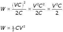
Now substituting for CV = VC = Q ,

Summarizing,

Capacitors in parallel
Capacitors in parallel have the same p.d. across them.
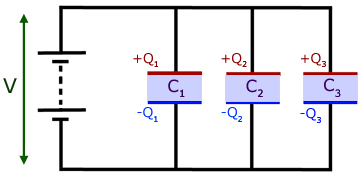
Writing Q = CV for each capacitor and adding :
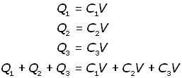
Putting QT as the total charge,
![]()
Hence,
![]()
Factorizing,
![]()
But
![]()
Therefore,
![]()
Capacitors in series
The battery removes charge Q- from plate 'a' and deposits it on plate 'f'. Plate 'a' is therefore left with a charge Q+on its plates.
Each charged plate then induces an opposite charge in its opposing plate.
The central capacitor C2 has a positive charge on plate 'c' because electrons are removed from it to make plate 'b' negative. Plate 'd' is made negative by induction with 'c'.
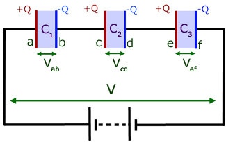
Making the p.d. V the subject for each capacitor and adding:
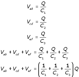
Summing the p.d. around the circuit, the supply p.d. is V is given by:
![]()
Hence

Recalling that,
![]()
By similarity, it follows that :

Charging & discharging a capacitor through a resistor
When the switch is closed charge from the capacitor flows through the resistor. The resistance R has the effect of limiting this flow.
For a fully charged capacitor of capacitance C let the p.d. be Vo and the charge Qo .
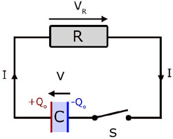
Consider the p.d. around the circuit at a time t seconds from the start of the discharge. Since there is no net p.d. in the circuit, by Kirchoff's 2nd law (relating to p.d. in a circuit) :
![]()
Quoting the capacitor equation, with V the subject,
![]()
Substituting for V in our initial equation,
![]() (i
(i
The current I is defined as the rate of charge of charge with time,
![]()
Remember the Ohm's Law equation,
![]()
Now, substituting for V and I into equation (i ,
![]()
Separating the differential operators dQ and dt ,

Since Q = Qo when t = 0 and Q = Q when t = t , integrating between these limits :

Hence,
![]()
Therefore,
![]()
and,

Changing into exponential form :

Rearranging into a more familiar form,
![]()
Substituting for Q = VC and Qo = VoC , cancelling the C's
![]()
So both the charge and the p.d. decrease at an exponetial rate.
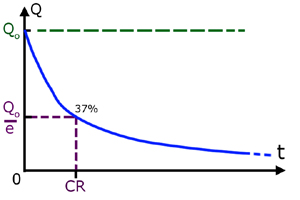
When the elapsed time t = CR the charge remaining is approx. 37% of the original amount.
![]()
The p.d. across the resistor VR and the current I through it are given by:
![]()

Note the minus signs in these equations.
This is a consequence of Kirchoff's 2nd law. Remember how the p.d. across the resistor and the capacitor are related.
![]()
If VR is taken to the other side of the equation it becomes negative. Hence one p.d. is the negative of the other.
The second equation (I) is obtained from the first by substituting VR = IR and rearranging.
The curve of Q vs t for charging is :

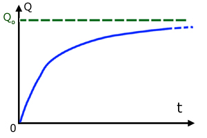
unfortunately lack of space precludes this derivation.
[ About ] [ FAQ ] [ Links ] [ Terms & Conditions ] [ Privacy ] [ Site Map ] [ Contact ]
