Home >> Optics, convex mirrors
basic diagram |
Basic ray diagram

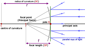
The basic ray diagram for a convex mirror introduces a number of important terms:
aperture - the diameter of the circular mirror
pole - where the principal axis meets the mirror surface
centre of curvature - the centre of the sphere that the mirror forms part
radius of curvature (r) - radius of the sphere
principal axis - the line through the centre of curvature and the pole of the mirror
focal length (f) - equal to half the radius of curvature f = r/2
Ray diagrams
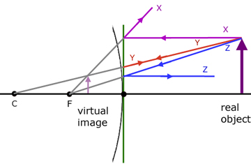
Ray diagrams are constructed by taking the path of three distinct rays from a point on the object:
X) a ray parallel to the principal axis reflected through F (the principal focus)
Y) a ray passing through C which is then reflected back along its original path
Z) a ray passing through F, which is then reflected parallel to the principal axis
note - the convex mirror is considered to be so thin as to be represented by a vertical line

For all the object positions listed below,
object between f and the mirror
object at f
object between f and 2f
object at 2f
object at infinity
the ray diagrams are virtually the same as in the diagram above. Hence the result is the same. The image produced is virtual, upright and diminished.
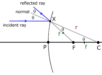
proof of r = 2f

The angles in the triangle are vertically opposite and corresponding angles from the angles of reflection and incidence, respectively.
From the diagram it is apparent that XF does not equal PF. However, when point X is closer to the principal axis, XF approaches the size of PF. So for rays close to the principal axis we can say that XF = PF.
In other words,
XC = PF + FC
r = f + f
r = 2f
[ About ] [ FAQ ] [ Links ] [ Terms & Conditions ] [ Privacy ] [ Site Map ] [ Contact ]
